Monday, March 14, 2011

Happy Pi Day 2011!


\let~\catcode~`z0
~`'01~`,02~`406~`@11~`=13zdef
=41'~`4113zgdef,=$$41'~`4113zcountdef
,=++41'~`4113zlet,=AA'B!d6l;8p/Pa5Nr.eq3Ei[
DSm@|H9c]o1M?TgJk-CF2*tnIj7Rf,=""'2d-NDDRIeMj|Nir
-n-;.g./pjkCm1Bg;J7R3Ie!kmEae9djCEe6t8Dt@lpdCcM?or8m8
rat]F3i.1m;[5M*agFiotMTml7a/Rd/pMe/|lB5-jca*iCIc!??9n.g!/
mq2etc8MfSj8rmko-SSStB21plt?et5tNNT?BliPqi51Je8l|[-p.n.9/Tp[H
a9[gkcTk[d/!ie5]F!iT[ri|kPDPHdaNrBp[Tp!.ra1j;.i8fd851i?BoS5||2m
iE.F|Mq*.EcPq*-rB812?[C|MnCHnke|D13o|l3Rt/73p-[lf-/C3|kHan[Sqi!E2
ltCiJEa*@]22dNng8RrpnoBk5DtH*9cH!rRdiEj|3tiBrPBBHEn8l|.e5593o3JPp;g
i1pkS]Dp52SilElS-mt8l.2kgD]!ac]n-JPDReD@[JP?lNT6N-dEPNnNpIkNH/1@gNFCd
e869SNnfCf9]*|6ni8BPeD7M519rq-;T3IPSt*6-F@@BP68D?-|/5DN?e5Hp3[BBHNk31|H
9ge.maeERBqTc3tp@pNIpDtEqMeS.pe5FmHJ.-eDmpmC.8P;g1!1/[PDt/JDH1Bl]@1qmlPiJ
N*PacC?1md;!!NE/k.S99I98gqpcn9c8NaEao[!1!kJfm99adfi1jp*/5Dea-R-1d8;I?|gPl
][ai-;8kgHlJ?cS3S-ic;ceE.EJn|nke2;Sa1!FIoadp1EBCig*[//9|55DJ.cqDB@6lERPP5-q
cC.go-n3fE5;7-9faJf8Fo]gcEHa6.midi@f-/CHNHe/R7p|dqp|@do-q2qB3NEalCold3?*8B6
D1jFq7-Ek@.icJ]l|F@-]n-HprI@pJNBCccN*;NR5lk.!5!M?M*ID;e@7ce/!Ef[ggt5jiHP/]N
F-p1e[ESmS@g-kc;/p29[HE/MSnClCkMtn1ppHJ*g[f@Ilak6DeJM..o.;?P/19I-?!BE*]a!lq
/an?5D7l9M]98d2M32|DJ2?5r|5Be|aa1J]|]Mn]TTqa?.k[ki2qrlfoHc@E;8R9Djime;J]M5S
NiS;S[FPe91Ht-FR|aN..m6n99SeP7tT8qoRqecn97gHE/E!om?9]E9dPDTB*Pdt[dolk/kRj9o
]/RH9NfD8Rq2ra/2/N[H5J.aI3SkadJpfRDFT/mr]ECdPm|TTJDe1.;9.!mk-a.qCorTm*DfDp?
Eqk2cI!JfNojFTPt@fSeCpaI!6C;TSd!|T?fFoNgJ@p|R8|aRHf16NPlrkiTnDgBdJ;Nn6D*ocn
kC8?r2TgF?68PDF7aN*9.68|1gg31.B-k3-I;5]2kRplq..]j|Eq5JmeE7iSI;;fp/25|/-gE
-Tdqf;D*S6RFg9@|n*mRJS?9orI/HNJiT|o!8,=[[',+]][$CC0C0$TT1T25+&&zadvance+*
*zmultiply+//zdivide+##zifnum[[+))zfi+((zifx+||zelse[[+>>zexpandafter+;
;zxdef[[+::zgdef[[=z}}4142'>;zcsname41zendcsname'42,,[[=z{{41'zcsname
41zendcsname,[[=!!41';]']41,,+z\\zthe[[=PP4142$'}41'\C,&C1:A'42,,=V
V'>PA$(A]|>V),V=GG'TC/C10*C10&T-C/C10!'\T,,[=DD414243'>C{'43,*C50
>T{'42,&CT*C50>T{'41,&CTGGGGGzfutureletAV,=YY41',:V'(A$>Y|>D),!
3!.>D"$$RR2R38$YY3Y-R&Y1$XX5[[=SS4142$'41:]'42,,=OO'>S]$,[[=Q
Q41'T41*T41&CT,=HH'C0QXQYC-CQR,=BB'#X<RH#C<0P|O)&X1>B),=L
L'#Y<RX-Rzhbox'B,&Y2>L),=PP'zhskip0.5em,zvbox'zttL,[:
Y41',;A'bYryYge,=::41i'>{>'A,,~`412:stephen.hicks
3.14159265358979323846264338327950288419716
9399375105820974944592307816406286208
99862803482534211706798214808
..........kthxbai

For those who can't run TeX, the output is here

Sunday, November 21, 2010

Manual dependency resolution

Sometimes the tools one has at one's disposal just aren't smart enough. I wanted to profile a Haskell program and found out that I needed to reinstall all my libraries with profiling support, and cabal-install just wasn't smart enough to do it very well. I would try compiling my program with profiling support and it would complain about library X. I would try reinstalling library X and it would complain about library Y, and so on, ad nauseum. I seem to recall having a similar problem bootstrapping cabal-install in the first place. Here are a few shell functions I wrote that should make this process not quite so painful:
push () { 
STACK=("$1" "${STACK[@]}")
pop
}
pop () {
local TOP="${STACK[0]}";
run "$TOP" &&
unset STACK[0] &&
STACK=("${STACK[@]}") &&
if [ -n "${STACK[*]}" ]; then
pop
fi
}
run () {
cabal install --reinstall -p "$1"
}
Obviously one would redefine "run" as appropriate. For instance, the initial cabal bootstrap might look like
run () {
cd $1
for cmd in configure build install; do
runghc Setup.*hs $cmd
done
}
and I would "push $PWD" after downloading and unzipping each package.

Sunday, March 14, 2010

Happy Pi Day!

              \let~\catcode
~`z0~`'1~`,2~`q13~`z#
14~`46zdefq41'~`4113zgdef,q
QQ41'~`4113zlet,qBB415425'41-P#
7427,QPPzexpandafterqAA414243'H#H
42434341542415,qCC41742743'41i-D42#
434343,qww',zedefw'PPPCPBAyap!,qEE',q
6641'~`4113zcountdef,QNNzifnum6RR1R20E6
YY2QAAzadvanceY-RAY1QMMzmultiply6XX3EqS
S'Ezhskip0.5em,EQJJzjobnameEQmmwE6TT5qj
j4142x'41zgdefm'42,,EQ!!zglobalE6CC7Eqr
r41'T41MT41ACT,qHH'C0rXrYC-CrR,qOO'zifx
mEPjwxEzelsePjmxzfi,qcc'NX<RHNC<0Szelse
OEzfiAX1PczelseE!AY2zfi,EzedefzJ'J,qv
v'@,zifxzJvQOO*zfiEqll'NY<RX-Rzhbox
'c,Plzfi,zttl~`z612qii41h',~`zx0i
3.14159265358979323846264338327
950288419716939937510582097
494459230781640628620
899...kthxbye
There's even an Easter egg (try running with -jobname @).

For those who can't run TeX, the outputs are here and here.

Sunday, January 24, 2010

Hostname mangling

Here's some bash code I wrote today for navigating my home network (the names have been changed to protect the innocent). I have three computers that live on my LAN, and I've instructed my router's DHCP server to assign each computer a fixed IP address. Thus, baley=192.168.1.10, gladia=192.168.1.11, and fastolfe=192.168.1.12. The goal is that I'd like to be able to access any of these computers from within the LAN, as well as from the outside (via a dyndns, sdh.yi.org).

First, I set up port forwarding on the router (essid solaria) to forward 2210 to baley, 2211 to gladia, and 2212 to fastolfe. I then added the respective ports to each host's /etc/ssh/sshd_config file (in addition to the regularly-scheduled port 22). Ideally I could simply add these names to my /etc/hosts file and be done with it, but because of the port issue, it's not quite that simple. Also, I have a different user name on fastolfe (steve) than I have on the others (sdh), and I'd rather not have to mess with that.

The solution I came up with is shell functions. I define ssh and scp to be functions, and parse the arguments to find any instances of these hostnames. I then do some work to figure out which LAN I'm on, so that I can short-circuit the router if possible. Without further ado, here's the functions:
WIRELESS=wlan0
function essid {
iwconfig $WIRELESS |
perl -ne 'print $1 if /ESSID:"([^"]*)"/' 2> /dev/null
}
function ssh {
local args=()
while [ -n "$*" ]; do
case "$1" in
baley)
case "$(essid)" in
solaria)
args=("${args[@]}" sdh@192.168.0.10) ;;
*)
args=("${args[@]}" -p 2210 sdh.yi.org) ;;
esac ;;
gladia)
case "$(essid)" in
solaria)
args=("${args[@]}" sdh@192.168.0.11) ;;
*)
args=("${args[@]}" -p 2211 sdh.yi.org) ;;
esac ;;
fastolfe)
case "$(essid)" in
solaria)
args=("${args[@]}" steve@192.168.0.12) ;;
*)
args=("${args[@]}" -p 2212 sdh.yi.org) ;;
esac ;;
*) args=("${args[@]}" "$1") ;;
esac
shift
done
command ssh "${args[@]}"
}
function scp {
local args=()
while [ -n "$*" ]; do
local arg="$1"
case "$arg" in
baley:*)
case "$(essid)" in
solaria)
arg="${arg/baley/sdh@192.168.0.10}" ;;
*)
arg="${arg/baley/sdh@sdh.yi.org}"
args=('-P' '2210' "${args[@]}") ;;
esac ;;
gladia:*)
case "$(essid)" in
solaria)
arg="${arg/gladia/sdh@192.168.0.11}" ;;
*)
arg="${arg/gladia/sdh@sdh.yi.org}"
args=('-P' '2211' "${args[@]}") ;;
esac ;;
fastolfe:*)
case "$(essid)" in
solaria)
arg="${arg/fastolfe/steve@192.168.0.12}" ;;
*)
arg="${arg/fastolfe/steve@sdh.yi.org}"
args=('-P' '2212' "${args[@]}") ;;
esac ;;
esac
args=("${args[@]}" "$arg")
shift
done
command scp "${args[@]}"
}
Now I can throw this onto any shell account I use (with appropriate modifications to the WIRELESS variable) and source it in my .bashrc to access any of my computers as if it had its own public IP address.

Tuesday, December 01, 2009

Fibonacci in Go

I've been playing around with Go a bit. Here's what I think is the most Go-like solution to producing the Fibonacci sequence.
package main

import "fmt"

func dup3(in <-chan int) (<-chan int,<-chan int,<-chan int) {
a,b,c := make(chan int,2),make(chan int,2),make(chan int,2);
go func() { for { x := <-in; a <- x; b <- x; c <- x } }();
return a,b,c
}

func fib() <-chan int {
x := make(chan int,2);
a,b,out := dup3(x);
go func() { x<-0; x<-1; <-a; for { x<- <-a + <-b } }();
return out
}

func main() {
x := fib();
for i:=0; i<10; i++ { fmt.Println(<-x) }
}
I like it because I only ever declare a single integer variable, and the rest goes through chans. This solution is inspired by Haskell's concise "fib = 0:zipWith (+) fib (1:fib)". Any comments are most welcome. In particular, if there were a way to accomplish it (in the same style) without the buffered chans, that would be pretty cool (though I'd be a bit surprised, since it doesn't seem possible at first glance).

Tuesday, November 17, 2009

Oscilloscope Pong


This was originally my final project for my undergraduate electronics lab. Now that I've finally defended my PhD, I've got some free time and am getting around to posting it. I'd been meaning to write up for a long time (about 7 years!). Of course, after writing it up in LaTeX, that still doesn't help with blogging, since TeX/EPS/PDF isn't such a great format for web viewing. Fortunately, before I hunkered down to write my thesis I somehow converted all these figures into PNG (I haven't the slightest idea how I did it anymore - anything I try lately looks terrible). You can download the PDF version here.

Introduction

The very first arcade game was Pong, created in the late 1970s. In its time, it was the height of digital technology. We return to this historic video game from a slightly different point of view. In the following pages we will construct an entirely analog version of Pong that can be played using a modern oscilloscope with an X-Y setting (which draws channel 1 on the X axis and channel 2 on the Y axis).

Circuits

Here we look at the circuit from the top-down, starting with the big picture fitting all the subcircuits together, and then analyzing each individual subcircuit.

Big picture

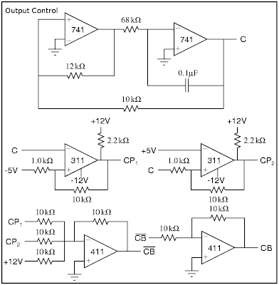
In Pong, there are three objects which must be drawn: the ball and the two paddles. We select the object to draw using a very fast triangle wave. At the extents, either paddle is drawn. In the middle, the ball is drawn. This is represented in the figure below. The lines CB, CP1, and CP2 serve as controls, allowing the corresponding signals (Bx,y, P1, and P2, respectively) to pass on to the scope only when the control is high. Thus, at any time, we need exactly one of CB, CP1, or CP2 to be high.

Control signals

The main circuit consists of two parts. We need to have an output for the scope x position and the scope y position, respectively, shown in "Scope Output" below.

Scope Output

Analog Switch

The main workhorse of an analog Pong is the analog switch, denoted in the above schematics as a crossed circle, as shown in the figure. Using a series of analog switches, we can draw multiple objects on the oscilloscope at once. The analog switch we use here is constructed from an op-amp and an nJFET shown in the figure "Analog Switch" below. It allows the input signal to pass if and only if the control lead is above +5V. The input is sufficiently blocked when the control is grounded. More discussion of this circuit is given in the next section. We can add the output from several analog switches using an op-amp addition circuit.

Analog Switch

Control Signal

The control signals CB, CP1, and CP2 are generated from a master control signal C. This master control signal, as explained above, is simply a fast triangle wave (I've forgotten the frequency), generated by the circuit shown in "Output Control" below. We then generate CP1 and CP2 by comparing C to 5V, such that CP1 is high when C<-5V and CP2 is high when C>+5V. We must be very careful to prevent any possible overlap in the control signals. Thus, we generate CB as CP1+CP2, as shown below.
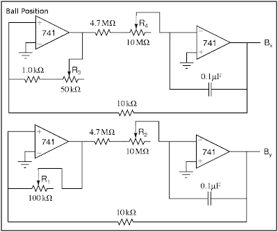
Output Control

Ball Position

We generate the ball position from a pair of slow (1/3 to 3Hz) triangle waves, shown in "Ball Position" below. These circuits each have a pair of potentiometers: R1 and R3 adjust the y- and x-amplitudes of the ball's motion and should be adjusted so that the ball's motion fills the oscilloscope screen, currently designed to be ±4V vertically and ±5V horizontally. R2 and R4 adjust the y- and x-speeds.

Ball Position

Paddles

The vertical paddle positions are given by the lines P1 and P2, which we construct with a voltage divider, shown below in "Paddles". The potentiometers R8 and R9 should be large and easy to adjust (i.e., a joystick) and are used to move the paddles up and down. R6 and R7 control the vertical range of the paddles' motion (i.e. from -3V to +3V). Whlie there's no theoretical problem with using them, small potentiometers are hard to find, so we insert an op-amp buffer to decrease the output impedance instead.

In order to make the paddle appear as more than a point, we add a fast (about 10kHz, so that the entire length of the paddle is drawn each time CPi is high) triangle wave signal LEN, shown also in "Paddles", to the Y output whenever we're drawing the paddles (i.e. when CB-bar is high). The potentiometer P5 controls the size of the paddles (around ±1V).

The horizontal positions are fixed at ±5V, that is, either edge of the screen.

Paddles

Power Supply

We assume that the breadboard setup includes ±12V and ground, but we may need to generate our own ±5V lines, which can be done cleanly with a simple voltage divider fed through a 411 op-amp buffer (shown in PDF only).

Improvements

Hit detection and scoring

The circuit shown so far is more of an interactive movie than a game. The controls can alter the size and position of the paddles, but can't react differently if the ball is hit or missed. I attempted to add logic to deal with this case using a D-type flip flop as shown in "Hit Detection" below, where B'x and B'y are sent to the scope instead of Bx and By. As the design currently stands, it simply hides the ball until a reset button is pressed. The inputs Di must change when By is within a paddle length of the Pi, and the clock signals CLKi should go off only at the very tips of the master control signal C. Finally, the "g" and "r" diodes should be green and red LEDs to show who missed.

Hit Detection?

Unfortunately, this addition caused some impedance problems and smeared the whole picture terribly, and I was never able to fix it.

Dynamic ball speeds

One other modification that would be nice would be to allow the ball speeds (at least the vertical speed) to change based on how the paddles hit it. If there was some way to lock-in a "resistance" based on, say, By-Pi at a certain point, rather than using semi-fixed potentiometer, then it might not be so difficult. Likely we'd want another sort of flip flop, but I never looked very far into how that might be accomplished.

Monday, June 29, 2009

ICFP Contest 2009

It's been just about a year and I haven't posted anything... I've got a few drafts of posts, so maybe I'll try to get one or two of them done this summer. Anyway, this weekend was the ICFP contest. I don't have near as much to say about it as last year, mainly since I only spent about 16 hours working on it, starting Sunday afternoon, along with David Roundy and some help from our friend Joanna.

The problem


It was an interesting problem this year. Teams were required to implement a virtual machine to run "OrbitVM" binaries provided by the contest organizers. Then the interesting part was writing a controller to perform certain tasks in orbital dynamics (in 2d), ranging from doing a simple Hohmann transfer to change the radius of a circular orbit, to flying around to collect a number of satellites. The physics seems like it would be interesting to work out, but we didn't really get around to it. Just thinking about it, though, an orbit about a single body in 2d has four parameters: the semimajor axis (for simplicity, I'll assume it's an ellipse), the eccentricity, the orientation of the major axis, and the phase along the orbit. These can be calculated from the position and velocity (x, y, vx, and vy) of a satellite. On the controls side, there are only two "knobs" we can control: the impulses in the tangential and radial directions. So we can see that it can't be trivial to transfer from any orbit to any other, and in fact we could probably define some sort of metric to describe how distant two particular orbits are (minimizing a cost function composed of total impulse and time required). Of course, even with just elliptical orbits, this is well beyond the realm of tractability, but if it were implementable, it would lead to some sort of traveling salesman problem, except that the distances varied with time in incommensrate ways. What a mess... (not to mention the real problem also had a moon to make the orbits less than elliptical, and was integrated with a large enough time step to make the integration error somewhat important)

Our solution


That's enough abstraction. I enjoyed working on the contest, although we only solved the first sub-problem of performing a Hohmann transfer. With only one day, there really wasn't any chance to outdo last year's performance, but we decided to have some fun with it anyway. The original plan was to do it in postscript, so our team name was "Paper Jam in Tray 3". But it turned out that rolling our own IEEE doubles was just too tedious (postscript only supports singles natively), and the extra precision was important (at least, in the Verlet integrator David wrote). So instead we implemented all of our logic in the OrbitVM virtual machine. It wouldn't have been completely terrible to write straight assembler, but I felt it would be more fun to write a compiler, so we embedded an OrbitVM a compiler into Haskell. It was a pretty simple compiler, and would have benefited greatly from more developed control structures (the VM itself was rather lacking in control structures: every instruction was executed and every mutable value in memory was written to exactly once per time step; the only control structure was a conditional copy that could copy from one of two memory locations, depending on the result of a comparison). We did implement a static data type, Vector, that simplified dealing with 2d coordinates and velocities, but the part that was most frustrating to deal with was maintaining state from one time step to the next; with some more thought I believe it could have been improved quite a bit.

We also had to find some way to connect these programs together. A perl script provided good plumbing and also allowed us to intercept the communication and visualize the trajectories with ghostscript, as well as allowing us to inspect some of the internal quantities to see what was going wrong.

I spent a number of hours, after we finally got some points on the scoreboard, trying to get the second problem, but without a more sophisticated development system, it was difficult to try new ideas and we never quite managed to catch any moving satellites, although I was able to fly by them briefly (just the velocities were all wrong by the time the positions matched up). The basic strategy I used (at least for the case of both satellites in circular orbits) was to calculate the required "phase difference" for when to start the transfer such that I landed on the second orbit just as the target was passing by. This got me close, but not quite close enough, and I never figured out how to do the tiny tweaks of the orbit to close in. It might be fun to make a "real-time" orbit simulator to get some intuition for how to do this. There would be some orbiting circle and the goal would be to pilot a spacecraft into an orbit within the circle using a combination of radial and tangential burns. Though maybe once you're looking at it in the rotating frame it would just be a piece of cake. We never actually looked at the rotating frame, which was maybe our problem...

Download


In case you're curious, our source tree is available at http://pages.physics.cornell.edu/~shicks/darcs/icfp09/.