This was originally my final project for my undergraduate electronics lab. Now that I've finally defended my PhD, I've got some free time and am getting around to posting it. I'd been meaning to write up for a long time (about 7 years!). Of course, after writing it up in LaTeX, that still doesn't help with blogging, since TeX/EPS/PDF isn't such a great format for web viewing. Fortunately, before I hunkered down to write my thesis I somehow converted all these figures into PNG (I haven't the slightest idea how I did it anymore - anything I try lately looks terrible). You can download the PDF version here.
Introduction
The very first arcade game was Pong, created in the late 1970s. In its time, it was the height of digital technology. We return to this historic video game from a slightly different point of view. In the following pages we will construct an entirely analog version of Pong that can be played using a modern oscilloscope with an X-Y setting (which draws channel 1 on the X axis and channel 2 on the Y axis).Circuits
Here we look at the circuit from the top-down, starting with the big picture fitting all the subcircuits together, and then analyzing each individual subcircuit.Big picture
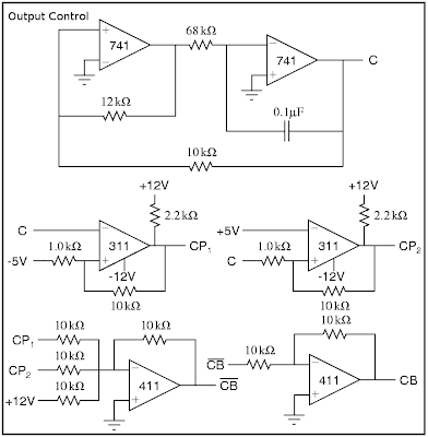
In Pong, there are three objects which must be drawn: the ball and the two paddles. We select the object to draw using a very fast triangle wave. At the extents, either paddle is drawn. In the middle, the ball is drawn. This is represented in the figure below. The lines CB, CP1, and CP2 serve as controls, allowing the corresponding signals (Bx,y, P1, and P2, respectively) to pass on to the scope only when the control is high. Thus, at any time, we need exactly one of CB, CP1, or CP2 to be high.
The main circuit consists of two parts. We need to have an output for the scope x position and the scope y position, respectively, shown in "Scope Output" below.

Analog Switch
The main workhorse of an analog Pong is the analog switch, denoted in the above schematics as a crossed circle, as shown in the figure. Using a series of analog switches, we can draw multiple objects on the oscilloscope at once. The analog switch we use here is constructed from an op-amp and an nJFET shown in the figure "Analog Switch" below. It allows the input signal to pass if and only if the control lead is above +5V. The input is sufficiently blocked when the control is grounded. More discussion of this circuit is given in the next section. We can add the output from several analog switches using an op-amp addition circuit.
Control Signal
The control signals CB, CP1, and CP2 are generated from a master control signal C. This master control signal, as explained above, is simply a fast triangle wave (I've forgotten the frequency), generated by the circuit shown in "Output Control" below. We then generate CP1 and CP2 by comparing C to 5V, such that CP1 is high when C<-5V and CP2 is high when C>+5V. We must be very careful to prevent any possible overlap in the control signals. Thus, we generate CB as CP1+CP2, as shown below.
Ball Position
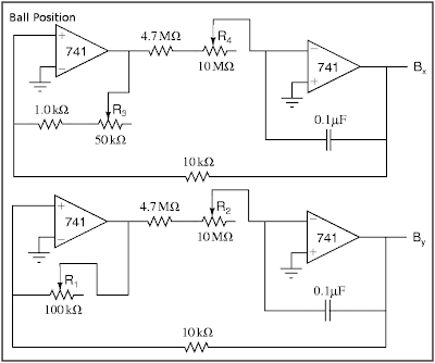
We generate the ball position from a pair of slow (1/3 to 3Hz) triangle waves, shown in "Ball Position" below. These circuits each have a pair of potentiometers: R1 and R3 adjust the y- and x-amplitudes of the ball's motion and should be adjusted so that the ball's motion fills the oscilloscope screen, currently designed to be ±4V vertically and ±5V horizontally. R2 and R4 adjust the y- and x-speeds.
Paddles
The vertical paddle positions are given by the lines P1 and P2, which we construct with a voltage divider, shown below in "Paddles". The potentiometers R8 and R9 should be large and easy to adjust (i.e., a joystick) and are used to move the paddles up and down. R6 and R7 control the vertical range of the paddles' motion (i.e. from -3V to +3V). Whlie there's no theoretical problem with using them, small potentiometers are hard to find, so we insert an op-amp buffer to decrease the output impedance instead.In order to make the paddle appear as more than a point, we add a fast (about 10kHz, so that the entire length of the paddle is drawn each time CPi is high) triangle wave signal LEN, shown also in "Paddles", to the Y output whenever we're drawing the paddles (i.e. when CB-bar is high). The potentiometer P5 controls the size of the paddles (around ±1V).
The horizontal positions are fixed at ±5V, that is, either edge of the screen.

Power Supply
We assume that the breadboard setup includes ±12V and ground, but we may need to generate our own ±5V lines, which can be done cleanly with a simple voltage divider fed through a 411 op-amp buffer (shown in PDF only).Improvements
Hit detection and scoring
The circuit shown so far is more of an interactive movie than a game. The controls can alter the size and position of the paddles, but can't react differently if the ball is hit or missed. I attempted to add logic to deal with this case using a D-type flip flop as shown in "Hit Detection" below, where B'x and B'y are sent to the scope instead of Bx and By. As the design currently stands, it simply hides the ball until a reset button is pressed. The inputs Di must change when By is within a paddle length of the Pi, and the clock signals CLKi should go off only at the very tips of the master control signal C. Finally, the "g" and "r" diodes should be green and red LEDs to show who missed.
Unfortunately, this addition caused some impedance problems and smeared the whole picture terribly, and I was never able to fix it.

2 comments:
I've tried to assemble this circuit, but there's something wrong with my LM311 comparator, it doesn't go to -12V as described in the circuit.
Hm, not sure why that might be. That said, I built this 13 years ago and haven't looked at an IC since. It's possible I transcribed it wrong, but wonder if maybe your chip is busted? Maybe test it in a smaller circuit where you know what the behavior is supposed to be?
Post a Comment